Classic vs. Planar Transformers
How Planar Transformers Benefit High-Frequency Switched Converters
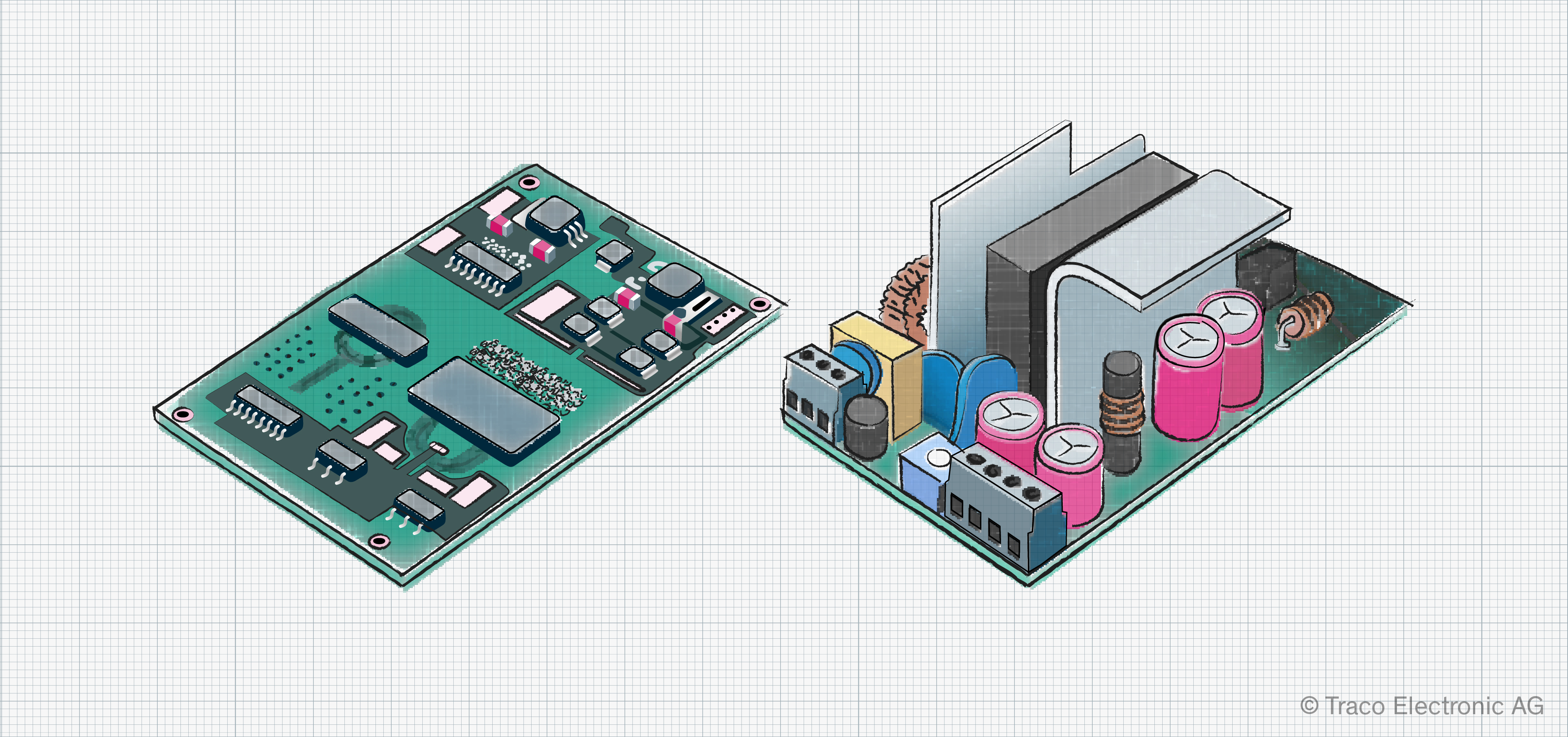
Open up any classic switching power converter, and one of the largest passive electrical components will be the transformer. With a metal core and a mass of copper windings, they stand proud of the circuit board essentially defining the power supply’s minimum physical size. However, consumers want flat TVs that can be hung on the wall and tiny, lightweight power supplies for their laptops. So, what can be done to shrink this bulky lump of metal?
Reducing the size of the transformer is no simple task, as we will see. And, until recently, there was little reason to do so. Switching power converters based on silicon MOSFETs and IGBTs typically operate at a few tens of kilohertz. This operating frequency defines the inductance of the wound components needed and, in turn, the size of the inductors and transformers used.
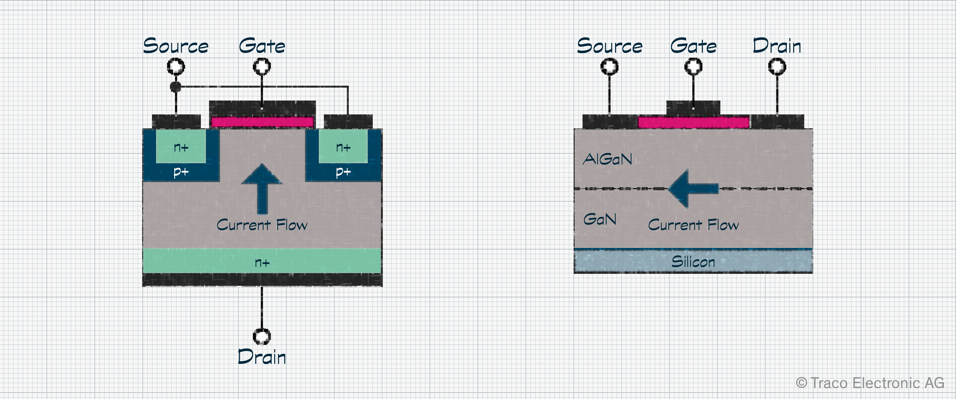
But this is slowly changing. With the introduction of wide bandgap (WBG) devices, such as SiC (Silicon Carbide) and GaN (Gallium Nitride), switching frequencies are increasing into the hundreds of kilohertz range and higher (Figure 1) driving the demand for smaller transformers.
How Are Conventional Transformers Constructed?
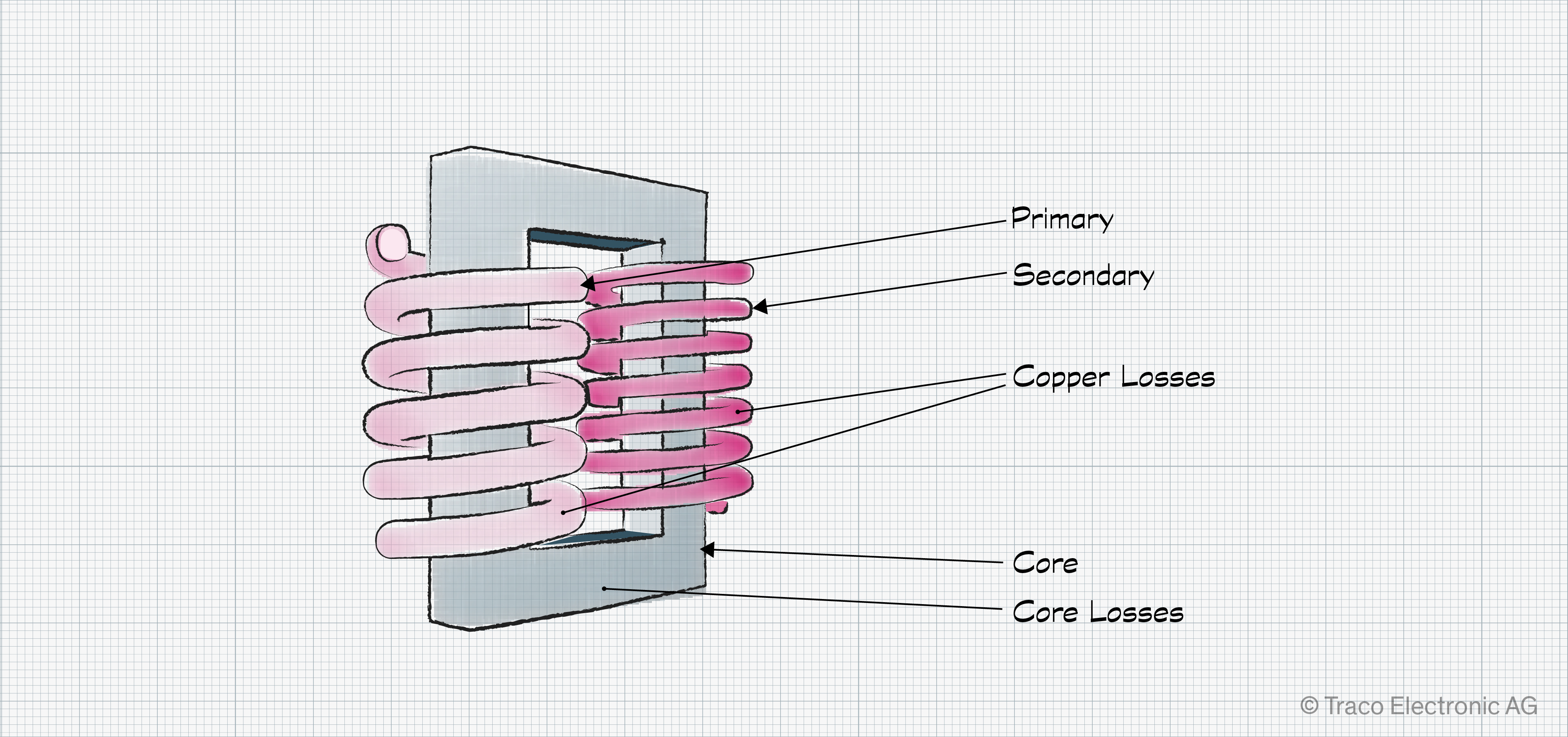
Before we can optimize these critical components, we first need to know how they are constructed and what their weaknesses are. The basic transformer typically consists of two closely coupled copper windings wrapped around a metal core. The incoming AC voltage is applied to the primary side. The same frequency signal appears on the secondary side at a voltage related to the ratio of turns. In a perfect transformer, power on the secondary side should be the same as that entering the primary side. But this is precisely where the challenges start.
During operation, unwanted eddy currents flow in the magnetic material, leading to losses. There is also some hysteresis in the continuously changing magnetic field. All these issues contribute to core losses. Windings and their ohmic resistance are the most significant contributors to losses, typically termed copper losses (Figure 2). The energy lost is converted into heat that must be dissipated using passive or active cooling.
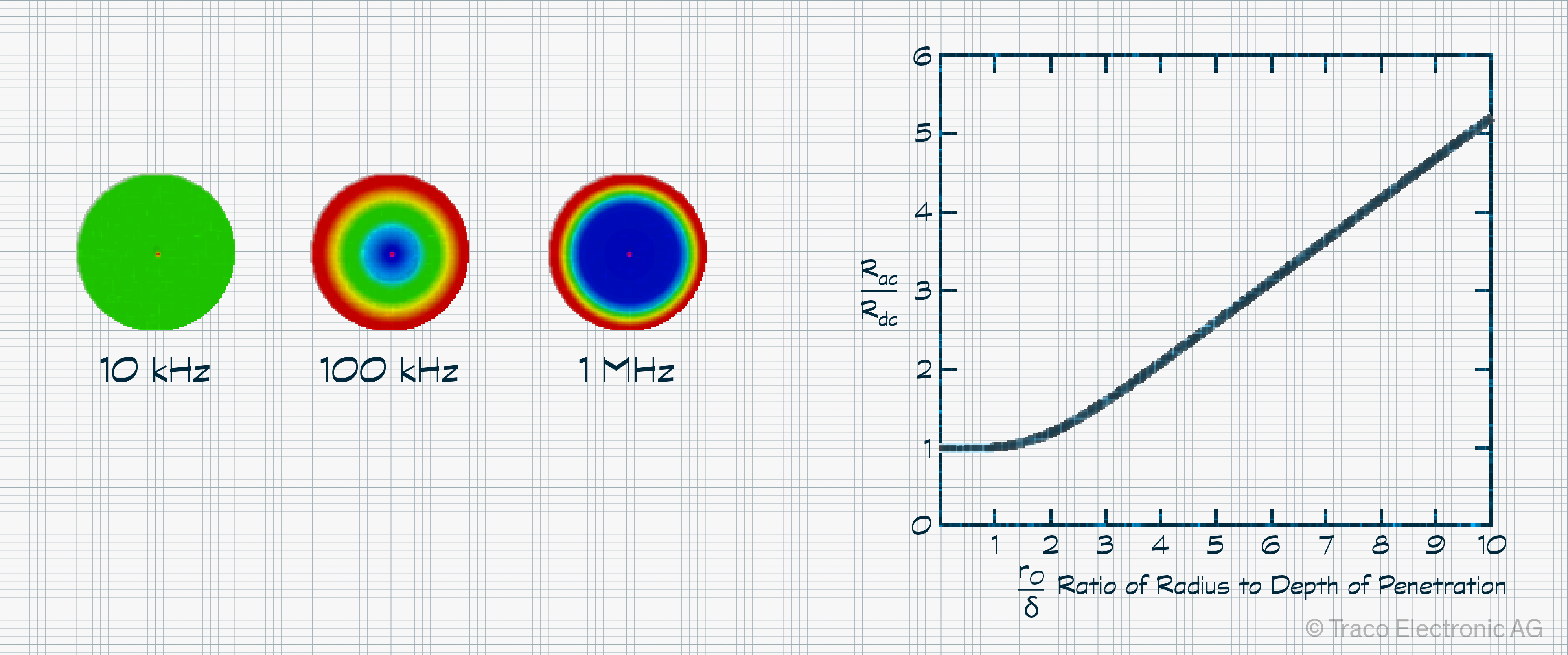
However, a new challenge arises as the operating frequency increases. We typically think of current flowing through a conductor, using all of the available area. However, this is no longer the case as signal frequency increases.
Gradually, the current is displaced towards the outside edge of the conductor, flowing across its surface. Known as the skin effect, this effectively reduces the current-carrying capability of a conductor (Figure 3). In turn, the wire’s electrical resistance is effectively increased, resulting in more losses and heat that requires dissipation.
This is why induction hobs use a wire with an increased surface area, known as litz wire, that consists of many strands of insulated thinner copper wire bundled to form a larger conductor.
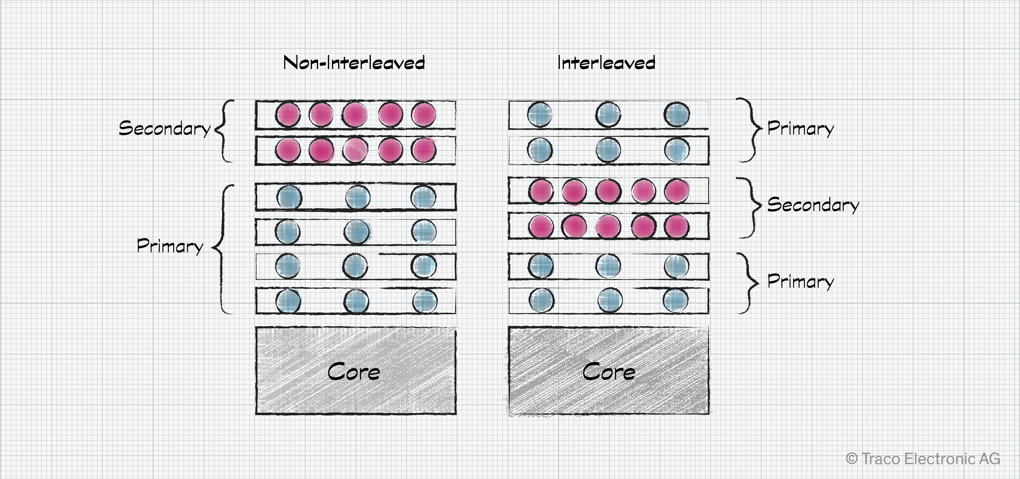
There is one additional source of losses. The current flowing through the windings generates magnetic fields during operation, but this field impacts the flow of current in neighboring conductors. This effectively increases the AC resistance, and the resulting losses are linked to the proximity effect. To tackle this, a construction method known as interleaving spreads the secondary windings between the primary windings (Figure 4).
From Conventional to Planar Transformer
To overcome the challenges listed, a handful of changes can be made to the design of a conventional transformer that helps reduce its size, reduce losses, and help with the dissipation of the remaining heat.
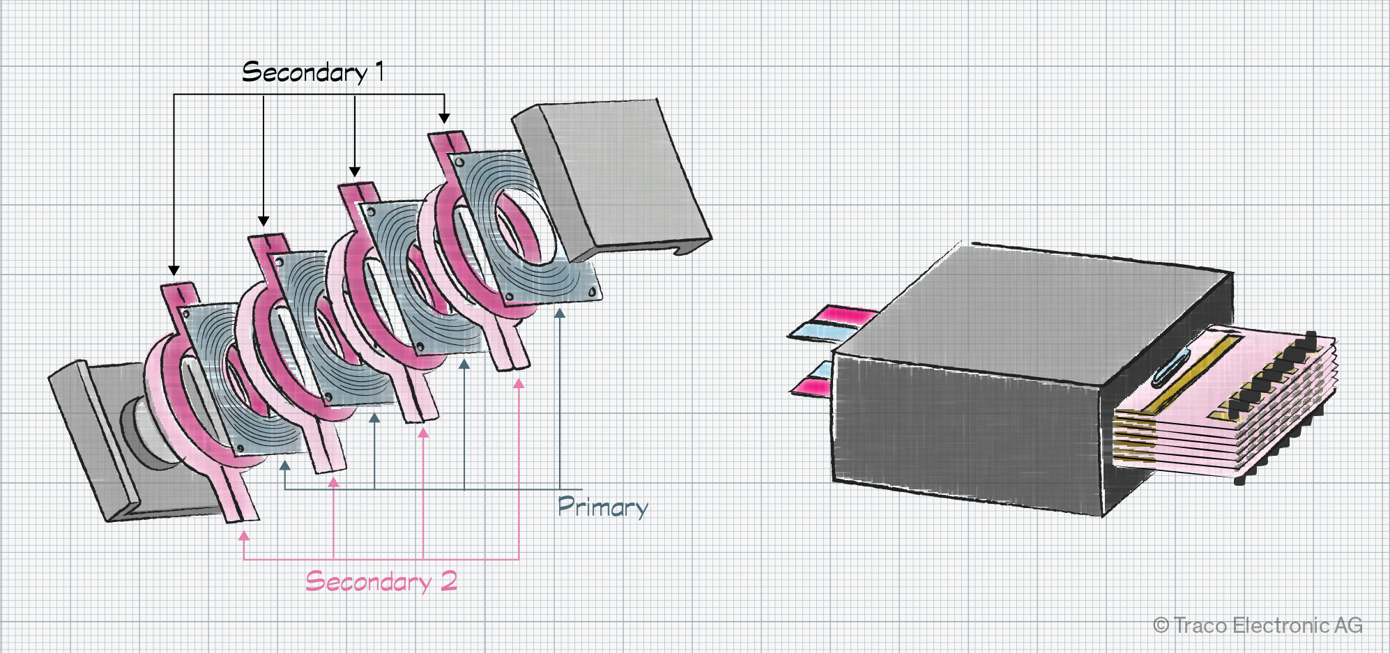
The first is to construct the windings in a manner that increases the surface area without increasing the cross-sectional area. Here, the approach is to use a flat conductor, such as the copper traces of a PCB or flexible printed circuit (FPC). This makes sense when considering that the skin depth for a 200 kHz signal is just 146 µm (5.7 mil). This implies a board with a copper weight of 0.12 g/cm2 (4 oz/sq ft) or less.
Such coils can then be stacked with regularly interleaving primary and secondary sides, helping to reduce AC resistance and the impact of the proximity effect.
This results in a much flatter design with performance parameters that better meet the needs of high-frequency switching power converters. In a side-by-side comparison, planar transformers also display a lower maximum operating temperature, achieving steady state faster. This supports the trend toward higher power density designs.
The planar transformer design is completed by using a core material chosen for its low hysteresis losses that supports a flat construction (Figure 5). In some cases, the transformer even becomes part of the PCB.
Are Planar Transformers the Future for Switching Converters?
It’s clear that conventional transformers can’t always meet the electrical needs of modern switching converters and, due to their bulk, get in the way of design aesthetics. Furthermore, such components have to be custom designed and are often hand manufactured, adding to the overall cost.
Planar transformers, by comparison, offer better performance at high frequencies and offer a flat form factor that can be integrated into the PCB and reduce EMC design challenges. The design also helps reduce the proximity effect and tackles the skin effect when compared to traditional transformers. New challenges do, however, arise. Coupling capacitance can cause issues that make the implementation of switching more complex, and the team may need to work through several PCB designs to ensure everything is optimized.
But the overall impact is very positive. Planar transformers not only save space, they ease the system’s thermal design, as shown in the design of a 70 W power converter (Figure 6). And, at a low number of layers, they are relatively straightforward to design, often integrating into automated manufacturing processes.