Simple Hold-Up Time Implementation for Railway Power Supplies
Simple Hold-Up Time Implementation for Railway Power Supplies
Railway applications, like most industries, have plenty of standards that have to be met. However, if you’ve never explored the requirements, you’ll be surprised at the extreme electrical conditions under which equipment is expected to operate.
Power can be supplied from a pantograph, generator, or battery management system, and the input voltage range is exceptionally wide. For example, systems for a light rail vehicle may be expected to operate from nominal DC voltages of 24 V, 48 V, 96 V, or 110 V. As a supplier of such electrical equipment, you’ll want to cover this with a single, wide-input power converter.
Another challenge is the general electrical environment. The voltage supply can fluctuate between 0.6 and 1.4 of the nominal value. Thus, a single supply approach needs to support an input voltage of between 14 V and 154 V. Then there are supply interruptions, as defined in EN50155 – Railway applications - Rolling stock - Electronic equipment. If Class S3 is specified, the equipment must operate as specified when the input voltage drops to 0 V for 20 ms. This implies that a hold-up circuit is needed to bridge such disruptions.
Typical Power Supply with Hold-Up Approach
Today, most engineers would source an EN50155-approved 12:1, ultra-wide input voltage range DC/DC power supply. This ensures that only a single product needs to be tested, approved, and stocked to cover all customer needs. To provide the required 20 ms of hold-up, a simple circuit is then added to the input.
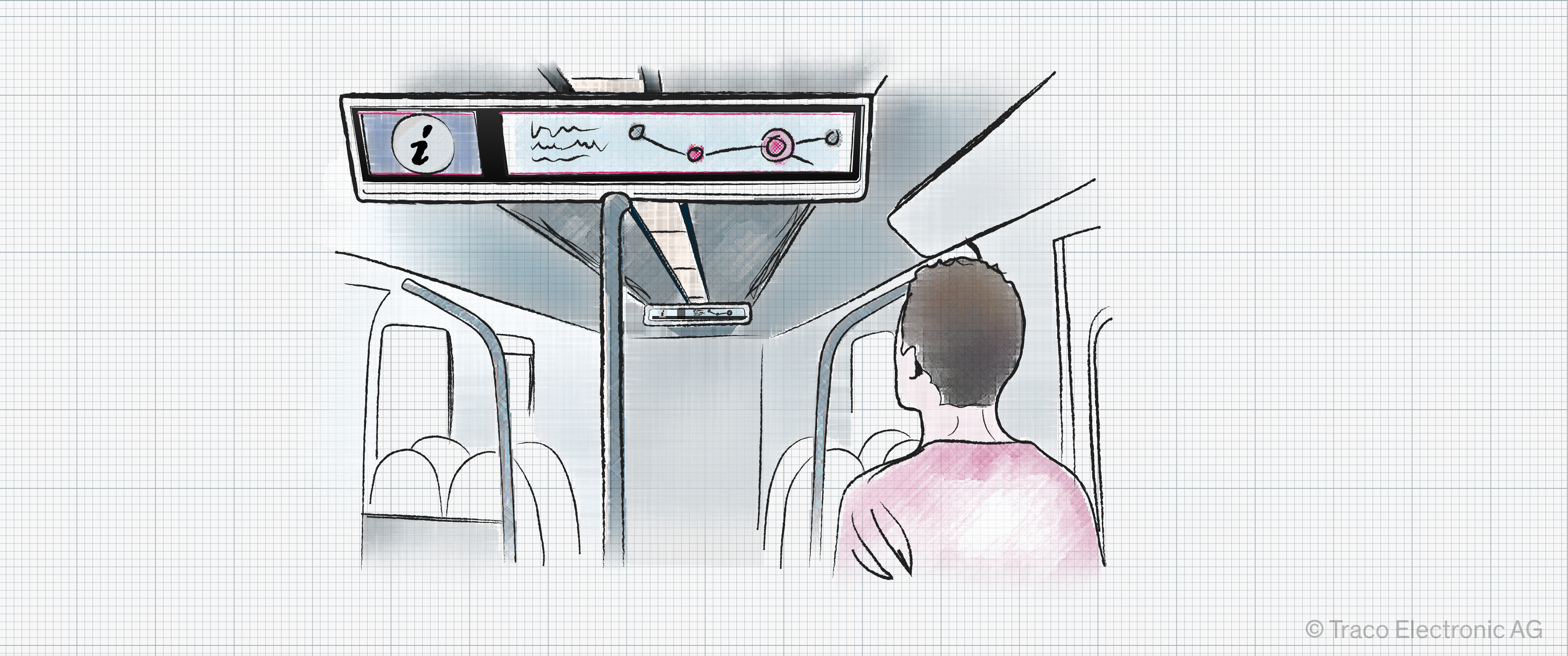
As an example application, assume that a power converter is required for a passenger information system (Figure 1). This includes a small screen, an embedded computing platform, and an industrial networking interface. The nominal power of this system is 40 W.
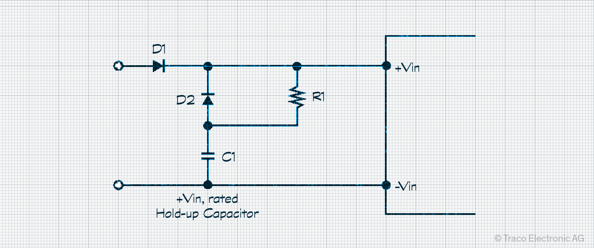
The first component, C1, is a capacitor (Figure 2). A series resistor is also required to minimize in-rush current (R1). However, this component must also be dimensioned so that the capacitor can recharge in a reasonable amount of time in preparation for any subsequent supply disruptions. Two diodes are also needed. The first, D2, ensures that the energy in the capacitor is delivered to the power supply in the event of a supply interruption. The second, D1, prevents accidental damage in the event of input voltage reversal.
The minimum hold-up capacitance can now be calculated, as shown in Figure 3. A factor of 1.5 is included to accommodate for component tolerances. Additionally, the worst-case power conversion efficiency (Eta wc), the application’s nominal power draw (P nom), nominal supply voltage (V nom), and lowest operational input voltage (V uvlo) are needed. The hold-up time (T hold) completes the required information.
Assuming a nominal supply voltage of 24 V, undervoltage lockout (UVLO) of 14.4 V, and a converter efficiency of 93%, this approach requires a minimum capacitance of around 7,200 µF.

However, because the capacitor sits at the input to our power converter, we have to accommodate a potential maximum transient voltage of up to 154 V. To ensure some margin, capacitors rated to 200 V would be selected. To keep the solution cost-effective, several 200 V rated capacitors would be combined to achieve the required capacitance, such as sixteen 470 µF components. This demands significant board space and volume to accommodate so many components and is a substantial cost adder.
Power Converters with Integrated Hold-Up Support
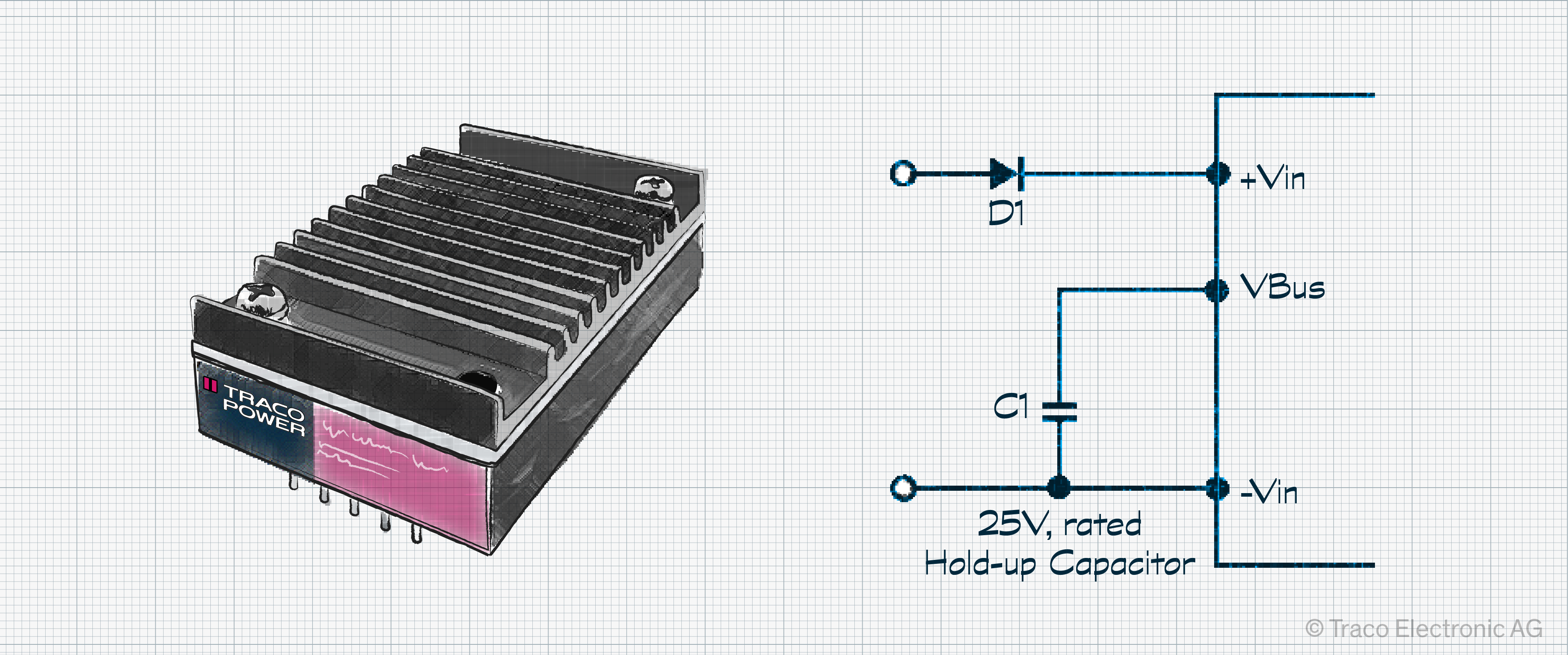
In recognition of these challenges in railway applications, some DC/DC power converters integrate most of the hold-up circuitry, simplifying the implementation. For example, the Traco Power TEP 40UIR series are dedicated DC/DC railway converters with a 12:1 input voltage range of 14 V to 160 V. They also feature a Bus pin for hold-up capacitors that can be dimensioned to the application’s needs. However, because the Bus pin only requires a pre-defined voltage of 21.4 V, capacitors rated to 25 V can be used regardless of the applied input voltage.
Furthermore, since the hold-up circuitry is integrated, there is no need for the external diode (D2) and in-rush resistor (Figure 4).
The same formula is used to simplify a comparison of the two approaches. We can assume the same power converter efficiency (93%) and UVLO (14.4 V), changing only the nominal supply voltage to 21.4 V. This results in a marginally higher hold-up capacitance of around 10,600 µF. However, only two cost-effective 25 V, 6,800 µF capacitors need to be sourced, taking up significantly less board space and requiring around fifteen times less volume.
Dedicated Hold-Up Support Simplifies Railway Power Supply Design
Selecting power converters for railway applications is challenging. Despite the wide input voltage range, application developers want to simplify their design effort and sourcing challenges by selecting an ultra-wide input supply that can cover all eventualities. However, the next complication is fulfilling the required hold-up time. Building a hold-up circuit connected directly to the power converter’s input means selecting capacitors with a high voltage rating. Thankfully, there are power converters with integrated hold-up support, such as the TEP 40UIR series. These allow lower voltage-rated capacitors (25 V) to be used that match the application’s requirements while delivering a lower capacitor cost and more compact design.
For more information on hold-up capacitor selection, startup and shutdown adjustment, EMC considerations, and other design tips, you can download the associated application notes here: TEP 40UIR application notes.